
This is the most ambitious personal project I have attempted. I plan to build a version of the InMoov robot and document my experiences here.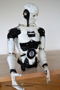 The InMoov is the creation of French sculptor Gaël Langenvin. Gaël has generously contributed the design as open source (for non-commerical use) including all of the 3-D design files and code.
The original design utilizes two Arduino processor cards and a Windows computer running MyRobotLab. I want to utilize the open source Robot Operating System to leverage the advanced architecture and existing features. I really like the ability to scale the use of additional heterogenous controllers throughout the robot while using the ROS. In order to use the ROS, the robot needs to run a version of Linux. This led me to decide to use a Raspberry PI 3 running Raspbian (Jessie) as the main processor. This latest version of the Raspberry Pi has some pretty impressive specs for such an small and inexpensive controller including quad core 64 bit processor, 1 Gig of memory, built in wifi and bluetooth, Micro SD card slot, 4 USB ports and HDMI to name just a few.
To get started, I plan to first build the right forearm and hand. Because I am starting with a processor and operating system that is different from the InMoov project, I plan to start small and build incrementally.
Getting the Raspberry Pi 3 OS Installed
After I received the the Raspberry Pi 3 (see the parts list below), I wanted to first verify that I could get the Raspbian operating system properly installed. This turned out to be very easy thanks to the excellent download and set-up instructions on the Raspberry Pi web site. I used a 16G Micro SD card I had on hand along with a bluetooth mouse, USB keyboard and HDMI display to boot NOOBS and install Raspbian. The ROS is rather large, so a 16 Gig Micro SD card seemed prudent. In very little time, I had the full desktop up and running. Afterwards, I learned of a innovative product called pi-top that turns your Pi into a laptop with integrated display, keyboard and mouse. This might be a good way to do standalone development on the Pi, although as you’ll see later, I found a wireless alternative.
Connecting a Servo
I had a very modest second step of getting a single servo to work with the Pi. There will be 28+ servos in a completed robot, so I thought I better figure out how to make those work right away. As a design principle, I decided to try to reserve the central Pi processor for high level functions and leave hardware protocol handing (e.g. such as pushing pulses to control servos) to other controllers. After some research, I selected the Adafruit 16-Channel 12-bit PWM/Servo Driver – I2C interface – PCA9685 because it off loads the pulse modulated width handling off of the Pi and uses the I2C interface to minimize the use of GPIO pins. It can handle up to 16 servos and additional boards can be chained together to support up to 992 servos. Yeah. That should scale just fine. This board requires soldering about 40 pins to make the connections. I also needed a way to connect the GPIO pins on the Pi to the servo driver board. I got a Pi T-Cobbler Plus – GPIO Breakout to do that. I used a servo I had on hand and these instructions to connect everything.
Configuring the Pi
For this design, I had to enable and configure wifi to connect to my local network and enable the I2C interface. I verified the wireless connection by opening the web browser included with Raspbian and connected to a website. I used these instructions to enable and verify the I2C function and servo board connection. I also changed the default password for remotely accessing the Pi.
Running the Code to Move the Servo
When I used the Pi with a monitor, keyboard and mouse I found the response time to be sluggish. I couldn’t see myself doing development work in that kind of environment where you want very fast response and build times. The ultimate solution would be to set up a cross-compile tool chain so that I can develop and build code on my Mac and deploy it to the Pi. This looks to be a complex process and so I elected to take a simpler approach.
Many Pi developers use the command line editors like nano or vi. I wanted something a bit more capable and came across the Adafruit WebIDE. This free tool runs as a server on the Pi and enables you to use a browser-based IDE on your computer to develop, build, test and debug your code. It uses a local GIT repository on your Pi to hold your code and backs it up to a BitBucket account.
I was able to run the Adafruit example Python code to test the servo without much trouble.
Next Up: Installing the Robot Operating System
Parts List
- [$40] Raspberry Pi 3 – Model B – ARMv8 with 1G RAM
- [$8] Assembled Pi T-Cobbler Plus – GPIO Breakout – for RasPi A+/B+/Pi 2/Pi 3
- [$15] Adafruit 16-Channel 12-bit PWM/Servo Driver – I2C interface – PCA9685

One thought on “Building a 3-D Printed Robot – Part 1”