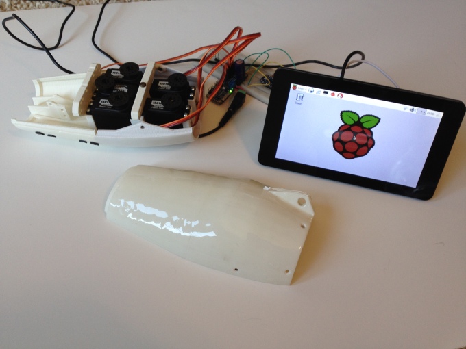

Since my last update, I have been able to assemble the hand and arm. Perhaps the trickiest part was threading the finger control lines through the wrist and forearm to reach the servos.

I elected to use the dual track servo wheel created by Mats Önnerby and available here. The dual track servo wheel is designed to provide a uniform tension on the tendons. Other solutions have involved the use of springs to maintain tension which still may be needed depending on the results of tension calibration. Calibration is the determination of the range of servo rotation needed to open and close each of the fingers. This will be interesting because the rotation of the wrist can change the tension depending on the degree of wrist rotation. Because of the iterative nature of this termination, I’ve elected to create a Python-based user interface to change the servos interactively. This post describes how I’ve built this user interface.
Building a Python-based GUI for ROS
This implementation use the Robot Operating System (ROS). The ROS provides a flexible control panel called RQT that enables prebuilt or custom plugins to interact with the rest of your ROS-based robot. There are quite a few existing plugins to monitor messages, logging, etc. It’s called RQT because it is based on the powerful UI framework called Qt and the Python bindings for Qt4 are included in the ROS distribution.
There is a tutorial for building a custom plugin and it is among the most confusing documentation I’ve seen for ROS (poorly organized and written). It could be that I am still learning the details of Python and the documentation assumes a level of Python expertise I have yet to achieve. I’ve written this post partially for myself so that I can remember how to create additional plugins but also for anyone else who struggles to follow the ROS tutorial.
Designing the UI
My intent is to have the hand calibration UI run on the Raspberry Pi with the touchscreen, but that doesn’t mean the UI needs to be developed on the Raspberry Pi. I installed Qt5 on my Ubuntu virtual machine running on my Mac. This was very straightforward and I encountered no issues getting it up and running.
When a new project is created in Qt, you are asked to specify the base class for your user interface. The RQT requires that your user interface use the QWidget class as the base class. The Qt Creator is the WYSIWYG user interface design tool. Here is how it looks after selecting QWidget as the base class and designing the hand calibration user interface:

The left side of the Qt Creator includes the perspectives such as the Design perspective as shown. The Design perspective has the palette of layout constraints and various elements to place on the canvas. The canvas has your user interface design – the hand calibration user interface design is shown here. Below the canvas is the Signals and Slots Editor that enables you to connect simple event-based relationships. In this case, as each of the sliders move, the number next to the slider is updated to reflect the new value. On the right side is the widget containment hierarchy and the property sheet for the selected element.
Your interface design is stored in a *.ui file which is an XML document which describes the elements and property choices you made in the Qt Creator. This file is used by RQT to render your plugin. There are alternative tools such as PyQt that includes utilities to convert the *.ui file into Python that uses the Python bindings included in Qt. This approach only works with Python 3 and ROS uses Python 2.7, so don’t be tempted to take this route (I did and it took a while to sort it out). Now that we have a user interface file, it’s time to integrate it into ROS.
Building the RQT Plugin
Since I would like to run the user interface on the Raspberry Pi, I had to revisit the ROS installation. When I originally installed the ROS on the Raspberry Pi, I elected to install the ROS-Comm subset instead of the desktop version (that includes Qt) in section 3.1. This time I installed the desktop version and subsequently ran into several linker issues that required source code level patches to fix. Now my Ubuntu and Raspberry Pi installations are equivalent.
Here are my notes related to the ROS RQT custom plugin tutorial. A custom plugin is implemented with a ROS package.
- Create an Empty Package – this is trivial and the instructions are clear. The naming convention for plugins is apparently to use rqt_ as a prefix for the package name.
- Modify the package.xml – A default package.xml was created in the step above and needs to have the tutorial updates made without changes. The confusing ${prefix} string need not be updated with your package path or anything. The tutorial text should be copied and pasted into your package.xml file verbatim.
- Create the plugin.xml file – This part is a bit confusing because it requires knowledge of the code you have not yet written. Skip this for now and proceed to the next step. Come back to this once you’ve written the code:
- Here is how my plugin.xml looks after step 4:

- The class tag name attribute must match the class name in the code
- The type attribute should use <ROS package name>.<Python source file name (the module name)>.<Plugin class name>
- The rest of the XML results in a menu on RQT that looks like this:

- Write a plugin code – Since this is going to be in Python, you can ignore most of what is written in the tutorial for this step and proceed to the Python specific instructions entitled Writing a Python Plugin. A few points about these instructions:
- It’s not clear to the ROS and Python neophytes that it’s important to recognize that the source directory should be named the same as the ROS package (e.g. rqt_mypkg) and the source file name represents a Python module (e.g. my_module). These two names are important to know for the plugin.xml file updates.
- I changed the default source code:
- Changed the class name from MyPlugin to HandCalibrationPlugin
- Changed the setObjectName parameters for the plugin and the widget.
- Updated the ‘MyPlugin.ui’ reference to the name of the actual *.ui filename from Qt Creator. While the tutorial does not mention it (except in the code comments), you need to create a ‘resource’ directory within the package source directory and place your *.ui file into the resource directory.
- The section ‘4. Once code is done’ is in the wrong place. You cannot run your plugin yet until it is installed, so ignore this step for now.
- Go back an update the plugin.xml file now.
- Install & Run your plugin – The instructions are adequate provided you have a clear understanding of the resulting directory structure. Here are few notes:
- My directory structure is now this:
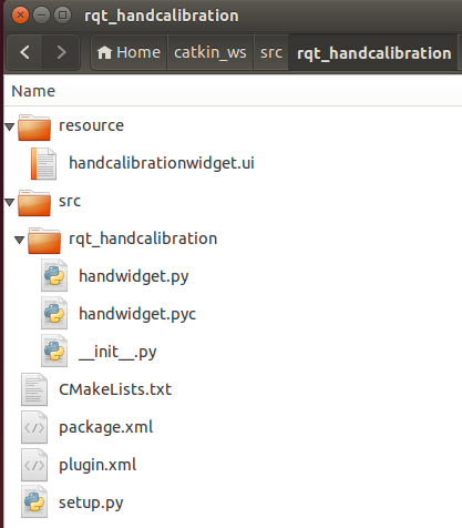
- The tutorial reference changes to setup.py and CMakeList.txt that are in your package source directory as shown above (e.g. src/rqt_handcalibration)
- The tutorial does not mention it, but I believe that you must also go to your catkin_ws directory and issue a catkin_make command.
- In order to run your plugin the first time, I needed to use the –force-discover option on rqt


The End Result
Now I have a ROS package that renders my calibration user interface that can run on my Mac or the Raspberry Pi. The distributed architecture of ROS enables me to run it on either platform.

Development Environment Note
My development environment is on an Ubuntu virtual machine running on my Mac. I’ve been using rsync as part of a build step to move files from Ubuntu to the Raspberry Pi. With the addition of a new ROS package, the build script now has two rsync commands. Until now, I’ve lived with the need to enter the password for the SSH connection rsync uses to connect to the Raspberry Pi. I found that this documentation was a pretty good explanation of how to configure SSH keys to enable a trusted connection without the need to supply a password.